Published By VITA 1600 Wilson Boulevard, Suite 500 Arlington, Virginia 22209 USA Tel: 703/276-1800 . Fax: 703/243-1865 Internet: pr-info@vita.org
Understanding Batteries ISBN: 0-86619-225-5 [C]1985, Volunteers in Technical Assistance
PREFACE
This paper is one of a series published by Volunteers in Technical Assistance to provide an introduction to specific state-of-the-art technologies of interest to people in developing countries. The papers are intended to be used as guidelines to help people choose technologies that are suitable to their situations. They are not intended to provide construction or implementation details. People are urged to contact VITA or a similar organization for further information and technical assistance if they find that a particular technology seems to meet their needs.
The papers in the series were written, reviewed, and illustrated almost entirely by VITA Volunteer technical experts on a purely voluntary basis. Some 500 volunteers were involved in the production of the first 100 titles issued, contributing approximately 5,000 hours of their time. VITA staff included Maria Giannuzzi as editor, Suzanne Brooks handling typesetting and layout, and Margaret Crouch as project manager.
The author of this paper, VITA Volunteer Horace McCracken, is the president of the McCracken Solar Company in Alturas, California. The co-author, VITA Volunteer Joel Gordes, is currently the solar design analyst for the State of Connecticut's Solar Mortgage Subsidy Program. The reviewers are also VITA volunteers. Daniel Dunham has done consulting in solar and alternative sources of energy for VITA and AID. He has lived and worked in India, Pakistan, and Morocco. Mr. Dunham has also prepared a state-of-the-art survey on solar stills for AID. Jacques Le Normand is Assistant Director at the Brace Research Institute, Quebec, Canada, which does research in renewable energy. He has supervised work with solar collectors and has written several publiations on solar and wind energy, and conservation. Darrell G. Phippen is a mechanical engineer and development specialist who works with Food for the Hungry in Scottsdale, Arizona.
VITA is a private, nonprofit organization that supports people working on technical problems in developing countries. VITA offers information and assistance aimed at helping individuals and groups to select and implement technologies appropriate to their situations. VITA maintains an international Inquiry Service, a specialized documentation center, and a computerized roster of volunteer technical consultants; manages long-term field projects; and publishes a variety of technical manuals and papers.
I. INTRODUCTION
Batteries have been in use for many years, but today there is a greater demand for battery power than ever before. This renewed interest has been brought about not only by new developments but also by the diversity of uses for batteries in civilian, industrial, and military applications.
This paper provides a basic understanding of batteries and traces their development from the early 1800s to the present day. Research and development continues in an effort to solve the inherent weakness of batteries, namely, how to pack more energy into a smaller package.
An electric cell or battery is a device that transforms the chemical energy contained within its active materials directly into electrical energy by means of an electrochemical reaction. This type of reaction involves the transfer of electrons from one material to another through a conducting solution. Historically, batteries played an important role in the early days of electrical development both in the United States and in Europe.
In 1800 an Italian scientist named Volta discovered that by immersing two dissimilar conductors in a chemical solution an electromotive force (EMF) or voltage was established between the two conductors. Figure 1 illustrates a simple Voltaic cell.
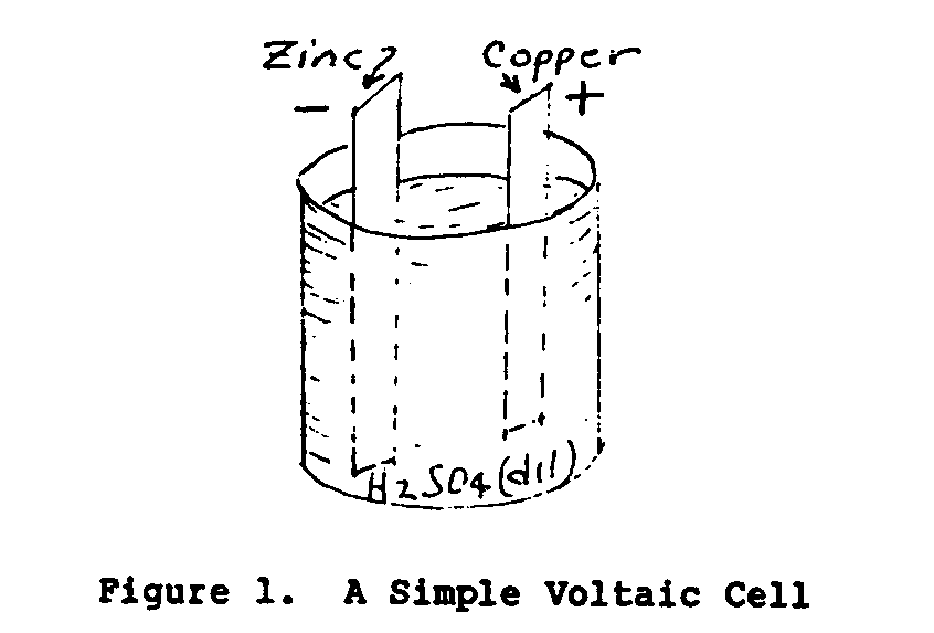
The solid conductors of the cell are called electrodes and the conducting liquid the electrolyte. A cell consists of two electrodes and an electrolyte. A battery consists of one or more cells. The voltage of the cell depends upon the material of the electrodes and the electrolyte. The electric current output and the power of the cell are dependent upon the plate dimensions and the weight of the electrode material.
There are two general types of batteries in use today: the primary type or "dry cell" and the secondary storage battery. A primary battery produces a current by discharge action when one of the electrodes of the cell is decomposed during use. This type of cell cannot be restored to use again by recharging and the entire cell must be discarded when it is no longer active. Secondary cells, on the other hand, are chemically reversible and can be charged and discharged over many cycles of operation before being replaced.
In the simple voltage cell shown in Figure 2, when two dissimilar
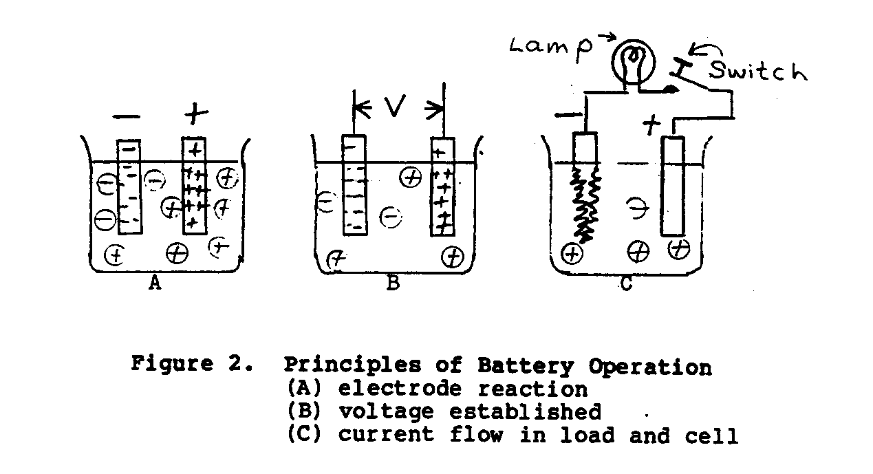
metals, zinc and copper, are suspended in an electrolyte of dilute sulfuric acid, a potential of approxiamtely 1.10 volts will exist between the electrodes. The zinc electrode will be negative and the copper electrode will be positive. When the switch in the external load circuit is closed, a current will flow through the load (energy-absorbing device) and battery in accordance to Ohm's Law.(*) As the load current continues to flow, hydrogen as bubbles will appear and cover the copper plate, and the zinc plate will gradually dissolve. The main disadvantage with this cell is that the gas bubbles increase the internal resistance of the cell, causing current output to decrease.
The direct current flowing in an electrical circuit is directly proportional to the voltage applied to the circuit. The constant of proportionality R, called the electrical resistance, is given by the equation V = RI, in which "V" is the applied voltage and "I" is the current.
II. TECHNOLOGY VARIATIONS
PRIMARY BATTERIES
Several different types of primary-type wet cells were developed and used in the United States. Most notable among these were the gravity cell, the caustic-copper oxide cell, the air-depolarized cell, and the Lelanche cell. Each cell had its own operating characteristics, and current capacities ranged from less than one ampere (amp) for the Lelanche cell to several hundred amperes for the caustic-copper oxide cell. The British Post Office developed a wet cell known as the Daniel's cell, which offered several outstanding operating features.
There were two main difficulties with the primary-type cell construction, deterioration by local action and cell polarization. Local action is an internal chemical action inherent to batteries; the life of the cell is gradually diminished even though no load is connected to its terminals. Local action is defined as the discharge of active material of either plate due to some impurity in the electrolyte or plate material. This action causes the formation of short-circuited cells, which cause the metal to deteriorate.
Cell polarization is caused by hydrogen bubbles being deposited on the cathode when current flows through the cell. This lowers the terminal voltage and increases the internal resistance of the battery. Various methods for neutralizing this polarizing effect were used, either by chemical or mechanical construction, which led to the development of the air-depolarized cell.
In the air-depolarized cell, the electrode was made of a highly absorbent form of carbon and was suspended above the electrolyte level. Since the carbon electrode was not immersed in the electrolyte solution, polarization of the cell was prevented. In operation, oxygen surrounding the porous surface of the carbon electrode combines with the hydrogen evolved at the surface of the carbon electrode and electrolyte. Good ventilation was required to maintain a satisfactory air supply for operation. The Edison carbon cell and the Carbonaire battery were representative of the air-depolarized type. Wet primary-type cells have largely been replaced by the secondary-type storage battery.
The modern day "dry cell," which was developed by Georges Lelanche in 1868, is a modification of the old Lelanche wet cell. The difference is that only sufficient water is added to the electrolyte to moisten an absorbent lining. The modern dry cell is the most widely used of all primary batteries today chiefly because of their low cost, reliable performance, and widespread availability. Dry cell batteries are made in ratings of 1.5, 3, 6, 7.5, 9, 22.5, 45, 67, and 90 volts.
The most common type of construction for a dry cell is shown in Figure 3.

The cell in Figure 3 uses a carbon rod for the anode or positive terminal and an outside zinc container (case) for the negative terminal. The zinc case has an inner lining of absorbent paper material which is saturated with the electrolyte. The space between the electrodes is filled with a mixture of crushed coke, manganese dioxide, and graphite. Manganese is added as a depolarizer. The electrolyte is salammonic and zinc chloride. The top of the case is sealed with a sealing compound and the zinc container is enclosed in a paper container. The voltage of a new dry cell is 1.4 to 1.6 volts.
Dry cell batteries fall into three general classes: (1) flashlight batteries usually 1-1/4 inch in diameter and 2-1/2 inches high with a current capacity of about 3 amp-hours; (2) large size cells, more commonly referred to as the Number 6 dry cell, approximately 2-1/2 inches in diameter and 6 inches high with a current rating of about 30 amp-hours; and (3) the "heavy duty" and high voltage types, which might be one cell or a combination of cells, used in industrial service with current capacities of 50 amp-hours or greater. The ampere-hour capacity is the rate of discharge a battery can maintain for a given period of time, usually eight hours. For example, a 30 amp-hour rated battery normally could supply about 3-1/2 amps for eight hours. As ordinarily used, however, dry cells provide less than their rating. The shelf life is limited by local action and for that reason some manufacturers stamp a service date on the outer covering of each cell. Local action causes eventual deterioration of the battery, and after about one or two years storage, the battery becomes useless. Since the zinc electrode forms part of the outer wall, its gradual destruction weakens the cell structure, and as the developed hydrogen gas builds up internal pressure, it can rupture and spill its corrosive contents. For this reason, equipment should never be stored with dry cells over long periods of time. Dry cells require no maintenance and when they no longer operate are discarded and replaced.
A more recent type of dry cell developed is the Ruben or Mercury cell (Figure 4). This cell was developed during World War II by
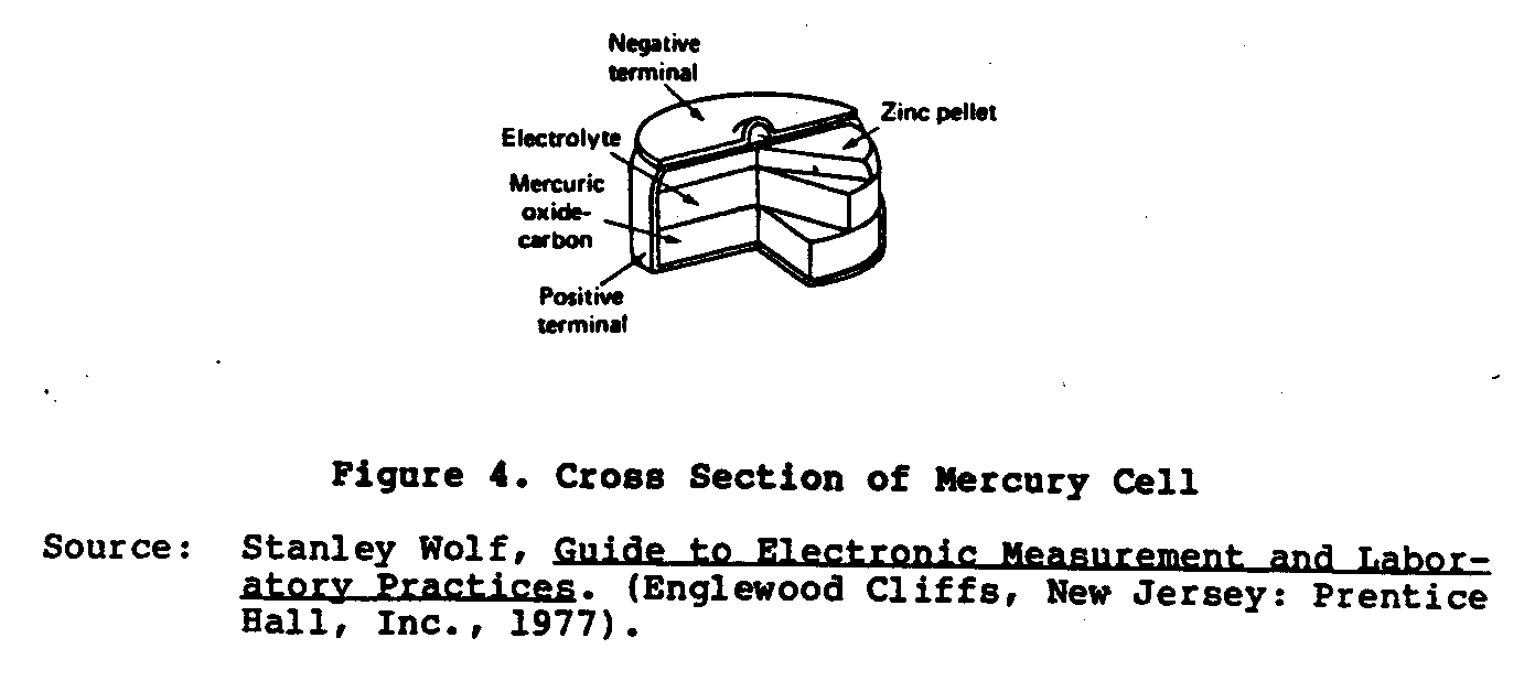
Ruben Laboratories and P.R. Mallory Company for operating small electronic equipment requiring high current power. This cell is made in two forms: the "roll anode" and the "button type." The anode is amalgamated zinc and the cathode is a mercuric oxide depolarized material mixed with graphite. The electrolyte is a solution of potassium hydroxide (KOH) containing potassium zincate. These cells are far superior to the Lelanche dry cell owing to their compact size, flat voltage characteristic, and very long shelf life. The no-load voltage of these cells is 1.34 volts.
Several advanced developments have been made in small batteries, both primary and secondary-type cells, which include the magnesium, alkaline, silver-zinc, and lithium. Table 1 lists the
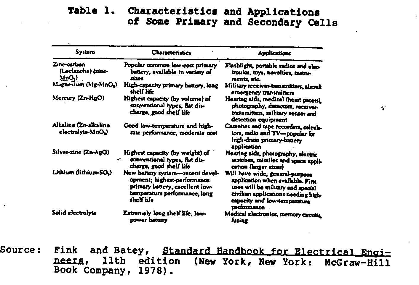
characteristics and applications of these cells.
SECONDARY STORAGE BATTERIES
Since 1965, there has been renewed interest in using storage batteries in power systems. This is because modern power consumption involves very uneven load demands and increasing peak load demands. When a system must deliver more power (increase in load demand), the supplier can meet the demand by either switching an additional generator onto the system or switching a charged battery bank onto the line. The latter requires a much smaller investment.
The revival of batteries as power system units primarily has begun with small independent systems such as wind- or water-driven generators. In such systems, storage batteries perform two important functions. First, during periods of low load demand, the system battery can store much of the generated energy, which would otherwise be lost to the system. Second, energy stored during the off-peak period is available during times of peak load demand. The importance of the latter can be illustrated with the following quantitative example: Suppose the capacity of the battery has a discharge power rate equal to half of the generator power capacity ([P.sub.B] = 0.5 [P.sub.G]). This means that under normal conditions, during periods of high load demand, the generator-battery combination can for several hours serve a load of up to 1.5 times what the generator alone could serve.
Another reason for the increased interest in secondary storage batteries is the need for backup power for some of the newer technology. For example, most modern computers involve some form of "volatile" storage of information, that is, the information is lost if power is removed. To guard against this possibility, many computer systems use "uninterruptible" power systems, based on storage batteries, to supply electrical current to the computer equipment when commercial power is lost.
The storage battery, constructed with secondary wet cells, is similar in action to a primary cell, except the chemical actions involved are practically completely reversible. Once the cell is discharged, current from an external source, passed through the cell in the opposite direction, will substantially restore the battery to its original charged condition.
There are three types of storage batteries currently available: (1) the lead-acid type; (2) the nickel-iron or alkaline battery (Edison cell); and (3) the nickel-cadmium or alkali-type (Nicad).
Lead-Acid Batteries
The lead-acid battery is the most widely used type of battery today because of its low cost, reliability, good performance characteristics, and wide application. This battery is manufactured in many sizes and capacities ranging from 1 amp-hour up to several thousand amp-hours rating.
The storage cell uses reactive sponge lead for the negative electrode (Pb), lead dioxide for the positive electrode (Pb0 ), and dilute sulfuric acid for the electrolyte. The electrode materials have little structural strength and must be supported on plates or grids. The grid of the battery plate has two functions: first, it supports the active plate material; and second, it serves as a conductor to connect the plate terminal to all parts of the active material.
Lead storage battery plates are divided into two types, the Plante (formed) and the Faure (pasted), as shown in Figure 5. In
the Plante-type of construction the active material is electrically formed of pure lead by an electrochemical process from the metallic lead of the supporting grid. In the Faure-type the active material is applied to the supporting grid in the form of a paste follwed by a setting, drying, and forming operation.
Figure 5 shows the Plante (A) and Faure (B) lead cell plates. The cell assemblies are soldered together to form positive and negative groups which are interleaved together to make up the complete battery cell. Separators are placed between the electrodes, and the complete element is placed in a container and sealed. The use of large plates with close spacing limits the internal resistance of the battery to a low level. Figure 6 shows a cutaway
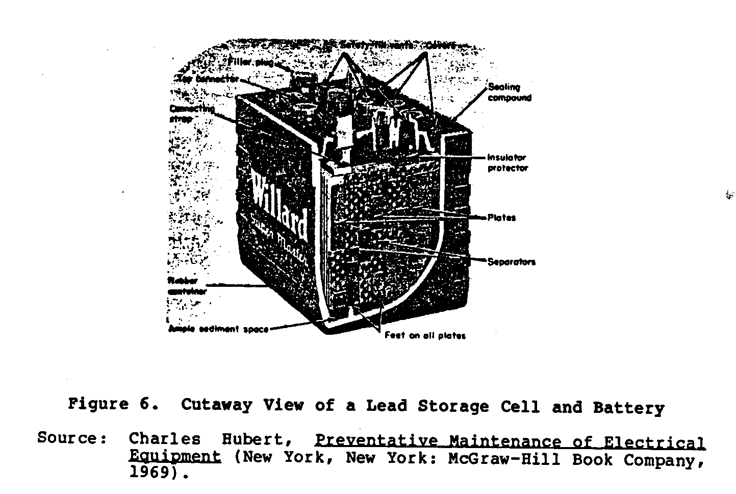
view of the lead storage cell.
During discharge the battery material of both plates is converted into lead sulfate. The amount of lead sulfate formed onthe plates and the amount of acid lost from the electrolyte are in exact proportion to the rate of discharge. The reverse action takes place when the cell is charged. Cell chemical reactions are represented by the following equation; however, this is a simplified form as the actual action is much more complicated.
Battery ampere-hour rating is normally based upon an 8-hour discharge rate.
At the positive plate:
Pb[O.sub.2] + HS[O.sub.4][sup.-] + [3H.sup.+] + [2e.sup.-](*) -----> PB[SO.sub.4] + 2[H.sub.2]O
At the negative plate:
Pb + HS[O.sub.4][sup.-] -----> Pb[SO.sub.4] + [H.sup.+] + [2e.sup.-]
The combined cell reaction for both discharge and charge is expressed by the following equation:
On discharge the acid separates from the electrolyte and forms a chemical combination with the plates, changing it to lead sulfate. As discharge continues, additional acid is drawn from the electrolyte until current will cease to flow. The water, formed by the loss of acid to the plates, lowers the remaining specific gravity(**) of the electrolyte. In common practice, discharge is always stopped before the plates have entirely sulfated, because once entirely sulfated, battery condition cannot be converted back to active material on charge. On charge the reverse action takes place: the acid in the sulfated plates is driven back into the electrolyte, and the S[O.sub.4] combines with hydrogen in the water to form additional sulfuric acid ([H.sub.2][SO.sub.4]).
Electrolyte for lead-acid cells is dilute sulfuric acid. For a fully charged battery the specific gravity varies from 1.200 to 1.30 and when discharged 1.150 (pure water measures 1.00). The specific gravity is measured by a syringe-type hydrometer as shown in Figure 7, and values are temperature corrected.
* The symbol e- stands for electrons.
** Specific gravity is defined as the ratio of weight of a given volume of a substance to an equal volume of pure water. The voltage of a lead cell is approximately 2.10 volts at no load but is higher when being charged. Normal voltage on charge is 2.15 volts and as the cell approaches full charge this value rapidly increases to between 2.5 and 2.6 volts. This later interval of charge is known as the "gassing period." Gassing of the electrolyte at any time during charging should be avoided as the charge rate is too high. As a cell reaches its final fully charged condition, a high current is not advisable as this excess current decomposes the water in the electrolyte, which is driven off in the form of gas.
The lead-acid battery has several disadvantages: (1) cells are temperature sensitive and lose power in cold temperatures; (2) cell plates tend to buckle and distort on sustained, high current service, and (3) special care must be observed when a battery is not used for long periods, otherwise the cells will sulfate.
Nickel-Iron Batteries
The nickel-iron or alkaline battery was developed to overcome the inherent disadvantages of the lead-plate cell. It is a radical departure from it in both construction and operation. In the United States this battery is known as the "Edison cell," named after its inventor Thomas A. Edison. Figure 8 shows the construction

of a typical cell. The positive plate consists of steel tubes containing nickel hydrate and nickel added in alternate layers. The negative plate is formed of flat steel boxes or pockets which are perforated and packed with iron oxide granules. Sheet-steel grids support these tubes and pockets, which are bolted together to form positive and negative cell groups. Cell terminals and the steel container are nickel plated. All separators and insulating parts are made of rubber. The cell uses an electrolyte of 21 percent solution of caustic potash containing a small amount of lithium hydrate.
The chemistry of this cell is quite complicated, and the chemical reaction occurring inside the cell is entirely different from that of the lead cell. The electrolyte acts merely as a conducting medium and does not enter into combination with any of the active plate material during operation. Its specific gravity remains practically constant over the complete cycle of charge and discharge. Condition of battery charge or discharge is determined by a voltmeter reading and not by the specific gravity of the electrolyte. The alkaline battery cell reaction is:
discharge ------------------> [Fe.sub.2] + 2NiOOH + KOH + 2[H.sub.2]O -------> [Fe.sub.2][(OH).sub.2] + 2Ni[(OH).sub.2] + KOH + electrical <------ <----------------- energy charge
The voltage of each cell is approximately 1.50 volts on open circuit, but is higher on charge and lower under load conditions. These batteries are given an ampere-hour capacity rating based upon their rate of discharge up to the final voltage of 1.00 per cell. Some current ratings are based upon a 5-1/2-hour continuous discharge rate, while others are based upon a 3-1/2-hour rate.
Unlike the lead-cell battery, there is no minimum voltage below which this type of cell cannot be discharged. In fact, this cell can be discharged to zero volts, short-circuited at its terminals, and left in this condition for an indefinite period. This is the method by which an alkaline battery is put into storage.
Also, this cell can be accidentally overcharged, charged in the wrong direction, and momentarily short-circuited without harm. Alkaline batteries are not injured by freezing and an electrolyte with a specific gravity of 1.200 at 15.5[degrees]C (60[degrees]F) freezes solid at -66[degrees]C (-87[degrees]F). The electrolyte of this cell gradually deteriorates during use and must eventually be changed.
The main advantages of the nickel-iron cell are: (1) it is extremely light and strong owing to its steel construction; (2) it offers an indefinitely long life; and (3) it overcomes the cell sulfating problem of the lead-acid battery. The chief disadvantage is its high first cost and high internal resistance.
Nickel-Cadmium Batteries
Nickel-cadmium or Nicad batteries, a relatively new addition to storage cells, were developed in Europe. These batteries consist of interleaved assemblies of positive and negative plates mounted in a sealed steel container. The positive active material, nickel hydroxide, and the negative active material, cadmium oxide, are encased in identical, finely perforated steel pockets. The plates are made up of rows of these pockets, which are crimped and formed into steel frames. Positive and negative plate assemblies are bolted together to heavy steel bus bars. Plate groups are interleaved and separated by thin plastic rods. The cell electrical terminals and case are nickel plated. The electrolyte is a solution of specially purified caustic potash (potassium hydroxide) dissolved in distilled water. Figure 9 shows a cutaway view
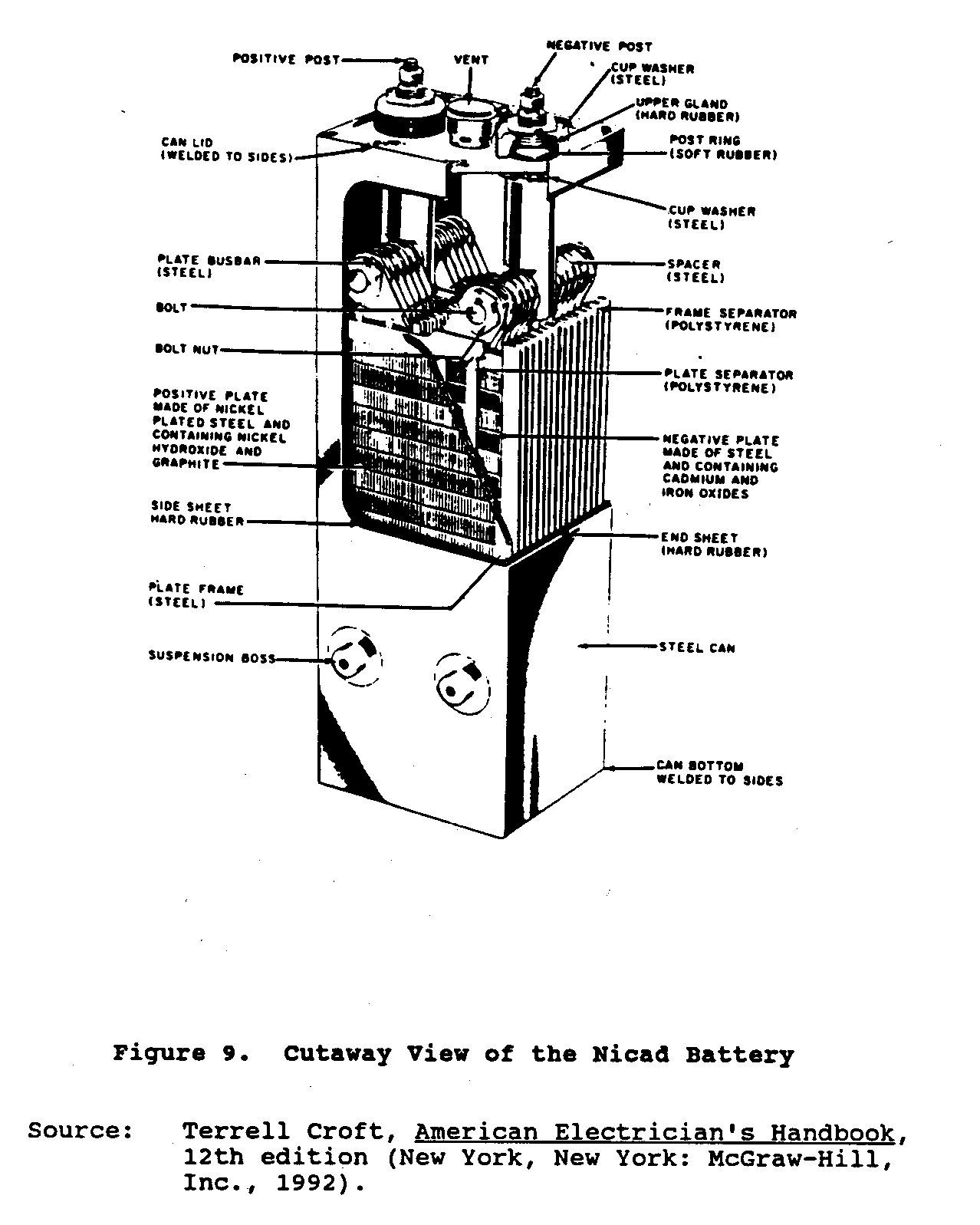
of the Nicad battery.
The simplified cell reaction is:
charge <------------------- Cd + 2NIOOH + KOH + 2[H.sub.2]O ------> Cd[(OH).sub.2] + 2Ni[(OH).sub.2] + KOH + electrical <------ energy --------------------> discharge
During charge or discharge of the cell, there is practically no change in the specific gravity of the electrolyte. Like the Edison cell, the sole function of the electrolyte is to act as a conductor for the transfer of hydrogen ions from one electrode to the other. The voltage rating of each cell is 1.20 volts on open circuit; when connected to an external load, this voltage remains fairly constant up to approximately 90 percent of its rated capacity. The amp-hour rating of the Nicad cells is based upon a final discharge voltage of 1.10 volts per cell. Unlike Edison cells, Nicad batteries will be damaged by repeated over-discharging below their minimum cell rating of 1.10 volts. Nicad batteries have a temperature operating range from -51[degrees]C (-60[degrees]F) to 93[degrees]C (200[degrees]F).
Nicad batteries are vibration and shock resistant due to their steel construction; hold their charge well during long idle periods; maintain a constant voltage source during discharge; and are not damaged by overcharge. These batteries can be mounted in any position on discharge. Like the Edison cell, the Nicad battery has a high first cost as compared with the lead-acid battery; however, this high cost is offset by their longer life span. A comparison of lead-acid, alkaline, and Nicad batteries is presented in Table 2.
Table 2. Comparison of Lead-Acid, Nickel-Iron, and Nickel-Cadmium Batteries
Operating Cell Life Typical Temperature Energy Charge/ Cell Range Density Discharge Cost Type Voltage ([degrees]C) (Wh(*)/kg) (Cycles) ($/Wh(*))
Lead-Acid 2.0 20 to 30 37 1200-1500 .08 Nickel-Iron 1.2 2.2 to 46 29 Nickel-Cadmium 1.25 (-51) to 93 33
* Watt-hours
General Maintenance Procedures for Storage Batteries
Proper maintenance is essential for continued trouble-free service of storage batteries. While the cell construction is different for the several types, maintenance is similar for all types and consists of the following general procedures:
1. Keep cells clean and dry;
2. Check electrolyte level regularly;
3. Keep batteries charged at all times; and
4. Keep impurities of all kinds out of cells as they will have a harmful effect and eventually ruin them. Never use any tools or utensils (hydrometers, funnels, etc.) that have been used to service other electrolytes different from that required for that specific battery, especially tools used for lead-acid batteries.
5. Refer to manufacturers' recommendations and keep a written maintenance record.
The electrolyte of the lead-acid cell never requires replacement except for loss due to accidental spills. However, in the Edison and Nicad cells there is a gradual deterioration of their electrolyte, which must eventually be replaced over the life of the battery.
BIBLIOGRAPHY/SUGGESTED READING LIST
Baumeister, T., ed. Mark's Standard Handbook for Mechanical Engineers. 7th Edition. New York, New York: McGraw-Hill Book Company, 1967.
Carr, C.C. Craft's American Electrician's Handbook. 8th Edition. New York, New York: McGraw-Hill Book Company, 1961.
Fink and Batey. Standard Handbook for Electrical Engineers. 11th Edition. New York, New York: McGraw-Hill Book Company, 1978.
Hubert, Charles I. Preventative Maintenance of Electrical Equipment. New York, New York: McGraw-Hill Book Company, 1969.
Knowlton, A.E., Standard Handbook for Electrical Engineers. 8th Edition. New York, New York: McGraw-Hill Book Company, 1949.
McGraw-Hill Encyclopedia of Science and Technology. 5th Edition. New York, New York: McGraw-Hill Book Company, 1982.
Timbre and Bush. Principles of Electrical Engineering. 3rd Edition. New York, New York: Wiley and Sons, Inc., 1946.
Wolf, Stanley. Guide to Electronic Measurement and Laboratory Practices. Englewood Cliffs, New Jersey: Prentice Hall, Inc., 1977.